- Home
- Product Categories
- 3-axis
- SparkFun Triple Axis Accelerometer Breakout - ADXL345

SparkFun Triple Axis Accelerometer Breakout - ADXL345
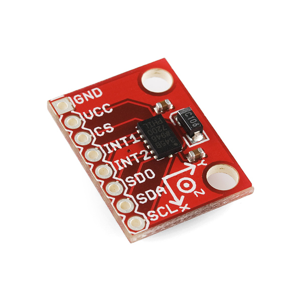
This new version adds two standoff holes as well as an extra decoupling capacitor. The ADXL345 is a small, thin, low power, 3-axis MEMS accelerometer with high resolution (13-bit) measurement at up to +-16 g. Digital output data is formatted as 16-bit twos complement and is accessible through either a SPI (3- or 4-wire) or I2C digital interface.
The ADXL345 is well suited to measures the static acceleration of gravity in tilt-sensing applications, as well as dynamic acceleration resulting from motion or shock. Its high resolution (4 mg/LSB) enables measurement of inclination changes less than 1.0 degrees;.
Several special sensing functions are provided. Activity and inactivity sensing detect the presence or lack of motion and if the acceleration on any axis exceeds a user-set level. Tap sensing detects single and double taps. Free-fall sensing detects if the device is falling. These functions can be mapped to one of two interrupt output pins. An integrated, patent pending 32-level first in, first out (FIFO) buffer can be used to store data to minimize host processor intervention. Low power modes enable intelligent motion-based power management with threshold sensing and active acceleration measurement at extremely low power dissipation.
- 2.0-3.6VDC Supply Voltage
- Ultra Low Power: 40uA in measurement mode, 0.1uA in standby@ 2.5V
- Tap/Double Tap Detection
- Free-Fall Detection
- SPI and I2C interfaces
- Schematic
- Eagle Files
- Hookup Guide
- Datasheet
- Example Code (ATmega328)
- GitHub
SparkFun Triple Axis Accelerometer Breakout - ADXL345 Product Help and Resources
Core Skill: Soldering
This skill defines how difficult the soldering is on a particular product. It might be a couple simple solder joints, or require special reflow tools.
Skill Level: Noob - Some basic soldering is required, but it is limited to a just a few pins, basic through-hole soldering, and couple (if any) polarized components. A basic soldering iron is all you should need.
See all skill levels
Core Skill: Programming
If a board needs code or communicates somehow, you're going to need to know how to program or interface with it. The programming skill is all about communication and code.
Skill Level: Competent - The toolchain for programming is a bit more complex and will examples may not be explicitly provided for you. You will be required to have a fundamental knowledge of programming and be required to provide your own code. You may need to modify existing libraries or code to work with your specific hardware. Sensor and hardware interfaces will be SPI or I2C.
See all skill levels
Core Skill: Electrical Prototyping
If it requires power, you need to know how much, what all the pins do, and how to hook it up. You may need to reference datasheets, schematics, and know the ins and outs of electronics.
Skill Level: Noob - You don't need to reference a datasheet, but you will need to know basic power requirements.
See all skill levels
Comments
Looking for answers to technical questions?
We welcome your comments and suggestions below. However, if you are looking for solutions to technical questions please see our Technical Assistance page.
Customer Reviews
3.9 out of 5
Based on 10 ratings:
1 of 1 found this helpful:
Worked on breadboard, but not when wired
I soldered the header pins to the board, plugged it into the breadboard, wired to the Arduino according to the instructions in the tutorial and got some nice readings. I wanted to move the accelerometer off the breadboard. So, I hooked-up some wires to the header pins and nothing worked. I tested the wires with my meter and everything seems to be working fine, but I only get 0,0,0 readings for the x,y,z values. I spent countless hours googliing this problem and apparently other folks have this same problem. It turned out that this was just another frustrating Arduino/sensor project that is glitchy.
Hi, Sorry, sounds like something is wrong in your setup. Since it worked in the breadboard, the sensor and code should be good. It is possible in changing the wiring, you may have damaged the sensor. However wiring a device should not be a issue or change the functionality if done correctly.
2 of 2 found this helpful:
Works well as a heel indicator for my boat
Once I got the math right and added some filtering this worked very well. I can get readings within a degree.
Here is the math in case anyone is interested
    double sq_term_y = sqrt(xx*xx + zz*zz);
    angle2 = 180 * atan2(yy,sq_term_y) / M_PI;
You might have to switch the terms around depending on the orientation of the device.
Here is the filter
double filter2pole(int index, double input){
static double filter1[3] = {0,0,0};
static double filter2[3] = {0,0,0};
double tc = .4;
double feedback = -.3;
double gain = 1 / (1 + feedback);
double sumOut = input + feedback * gain * filter2[index];
double difference = sumOut - filter1[index];
if (abs(difference) > 5){
    filter1[index] = input / gain;
    filter2[index] = input / gain;
}
else {
    filter1[index] += tc * (difference);
    difference = filter1[index] - filter2[index];
    filter2[index] += tc * (difference);
}
return gain * filter2[index];
}
I set the BW to .78 Hz which was good for my 1Hz update rate.
The only thing that took a bit of time to figure out is that the address select line floats low. I added a pullup resistor to get the default address (1D) but next version I will just pull it down and use the alt address
1 of 1 found this helpful:
Great Breakout
Personally, for my uses (purely registering hits and taps) the MMA8452Q breakout is a better deal, however this is a great breakout board with excellent accuracy and resolution. As a word of warning, I would protect is with a logic level shifter instead of using 5v logic but 3v3 VCC as recommended in the tutorial.
Finally it's working
It took a long time to reach my address. Anyway now its working with the basic code without adding any 500 ms delay (As one user reviewed to add 500ms in set up block. Thank you. #DIY
I am looking forward to develop FFT for vibration analysis with the same ADXL345 SPI Arduino R3 in the Mc.
Reliable building block
4 components, simple as that. using i2c sensing activity and freefall.
0 of 4 found this helpful:
Shield project error !!!! NO I2C CAPABILITY !!!!
It was necessary to add three 730Ohm resistor on CS, SDA and SCL connections to be connected to VCC. This 3 cent error has became a 400USD cost for me. Because it makes impossible to use I2C communication with the board "AS IT IS PROPOSED"... CORRECT THIS PRODUCT! As it is is simply Junk! And also the customer service to describe this simple issue HAS BEEN SIMPLY OFFENSIVE!!! no where is possible to read how to slove the issue. I've been able to explain it in two rows INSTEAD! Was it diffcult? It doesn't seem so to me! but I've losted 400 USD the same!
This product works fine over I2C. If you needed to add resistors, it sounds like you may be trying to run this from a 5V source, and it is a 3.3V board. I've searched your customer account, and can find no indication that you attempted to contact customer service or tech support. I would suggest getting in touch with our tech support team for guidance on the proper setup.
Solid-performing Accelerometer
Reasonable price and performance.
Works
Works very well on a SPI interface, no noise
B
Accelerometer worked great. Basic code was a nice accessory but had some errors. It desperately needed Instructions on how to change the mode to 16 G's. there is no way of knowing that I could tell. But overall it worked good.
Works great with 500ms Delay
Prototyped successfully with code provided. But got 0,0,0 when moved off the breadboard. Same story with Sparkfun Redboard and UNO r3. Now working solid with a 500ms delay at the end of the setup section. I believe this is a vital modification to the basic example program.
Hi, thanks for the tip. We'll take a look into this and make changes as needed. Happy hacking!
So I just realized that this chip needs to run at 3.3 v, I have been running it at 5 v for months. After switching it to 3.3 the z-axis only reports positive numbers, the other two axes are fine. Any idea why this is happening?
nice product. Worked fine
Has anyone gotten this to run on an Arduino Micro?
I just finished a rich, interactive register map on the I2Cdevlib project device page for the ADXL345 here:
http://www.i2cdevlib.com/devices/adxl345
My goal is to provide an easy, intuitive reference for working with this and other devices, and ultimately to make it easy to port (or generate) device control code across multiple platforms. Right now there is Arduino library and example code, but others are not far away.
Great, I was able to use some of you idea in my work. Thank you for sharing
This looks great, can't wait to use it!
You can find demo code using a sparkfun ADXL345 accelerometer breakout board with Tiva TM4C123 micro and Beaglebone Black here.
Also I have the demo's on youtube.
Most of the component are from sparkfun
Good luck
I have interfaced this accelerometer to my atmega1280 board (not arduino). Written program in atmel studio 6. I have configured it for 3200hz data output rate, fifo bypass mode, using full resolution and range is +-2g. I am getting values ranging from about -255 to +255 (only gravity acting, not any additional acceleration). Am I getting right value range? Or is there any way to get more resolution? And when still data is fluctuating +-5. Is this normal?
Accelerometers are notoriously noisy sensors, +-5 is not anything to write home about, you could try adding another small 1uF - 10uF cap to the power to see if it helps, but the wind blowing on your house with a wobbly table could make it wander still.
Gravity being 1G, my guess is that your reading of +-255 is a bit low, With 12-bit resolution (this chip states 13-bit) you should get a total range of 4096, which is +-2048. Unless I'm mistaken you should be seeing +-1024 from the effects of gravity (Half the total range of 2g).
Edit: After looking at the datasheet, you'll find that the higher bit resolution is for the higher ranges. For the 2g range it's going to get 10-bit resolution (1024 steps) which is +-512. In that case, gravity should give a reading between +-255, which is spot on with what you're showing.
Is there anyway to communicate with multiple ADXL345 via the same i2c bus? I am trying to communicate with 5 of these sensors
Thank you
Unfortunately by setting the "ALT ADDRESS" pin either high or low, you're only able to select between 2 addresses, making more than 2 chips coexist on the I2C lines impossible. I haven't looked to see if there are different versions at Mouser or Digikey that will allow different addresses to choose from, but it is a possibility.
Has anyone tried to interact with this breakout board via a bus pirate in SPI mode? I have connected the bus pirate to the ADXL345 breakout board and also connected a Saleae Logic Analyzer (e.g. I can see bus pirate driving SPI reasonably). The problem is I see no response from the ADXL345. The odd thing is when I toggle the power (bus pirate "W" and "w" command), the voltage varies between 3.3 and 2.5volts respectively. In other words, there appears to be some back current. I have tired this on two different ADXL345 breakout boards with the same results.
While I see lots of code using this device in I2C mode, I find very little on using in via SPI. Anybody have any insights into what is happening,...why the odd back current on Vcc when powered off?
BTW I am able to successfully interact with a LIS3DH accelerometer in SPI mode just fine with this same bus pirate.
Some details about my Bus Pirate Bus Pirate v3.a Firmware v6.1 r1676 Bootloader v4.1 DEVID:0x0447 REVID:0x3043 (xxxxxxxxxxxxx) http://dangerousprototypes.com
The Bus Pirate command sequence use for testing: setup and read DEVID register (0x00)
HiZ>m 1. HiZ 2. 1-WIRE 3. UART 4. I2C 5. SPI 6. 2WIRE 7. 3WIRE 8. LCD x. exit(without change)
(1)>5 Set speed: 1. 30KHz 2. 125KHz 3. 250KHz 4. 1MHz
(1)>4 Clock polarity: 1. Idle low *default 2. Idle high
(1)>2 Output clock edge: 1. Idle to active 2. Active to idle *default
(2)>2 Input sample phase: 1. Middle *default 2. End
(1)> CS: 1. CS 2. /CS *default
(2)> Select output type: 1. Open drain (H=Hi-Z, L=GND) 2. Normal (H=3.3V, L=GND)
(1)>2 Ready SPI>W POWER SUPPLIES ON SPI>[0x80,r] /CS ENABLED WRITE: 0x80 READ: 0x00 /CS DISABLED
I have been working with this thing. and even when I put it in sleep mode it seems to draw 53uA no matter what. When I set the bandwidth register to reduce it to 3Hz sampling(23uA) according to the data sheet it is at 72uA @3.1V. Can anyone tell me why this thing is chewing up the mysterious 50uA?
Ok got a weird question - I've been playing around with this sensor for awhile and was wondering if there was anyway to interpret the interrupt functions (specifically the free fall detection) without using a microcontroller.
Ideally I'd like to set the limits for free fall in the register using a mcu, disconnect the mcu, then be able to use the interrupt pin as a control (i.e. pin goes high -> turn on led or whatever, pin goes low -> turn off led). I'm thinking set up could be similar to how you initially set the time on a rtc then as along as you keep it powered it keeps an accurate time, but I'm not sure how reading and translating the interrupt register would work...
Thoughts?
I have no issues running the Arduino Basic example and get ~128DN on the Z-axis which corresponds to 1g. When I modified the example code to switch to +/-8g, I get nearly 0 DN on all axis and once every 100 measurements I see a 256 DN. All I changed was line 38 from 0x01 to 0x10. Has anyone seen this problem?
Im confused, which is more sensitive 250g or 2g? Sorry if the question sounds dumb!
Since you cross-posted, please see my comment in Single Axis Accelerometer Breakout Board - ADXL193 +/-250g for a reply. tl;dr: the 2g is likely to be more sensitive, but you'd have to check its specs closely to be certain.
hello, my name is Luis. I have a problem with arduino. I like to know if there is an ADXL345 updated library for the current version of Arduino. because i used the ADXL345 library for the arduino 022, but it does not function with a program that it was done in Arduino 022.
Hi I was wondering if someone managed to connect the sensor in 3 wire spi mode. I tryed to set the SPI pin on the 0x31 register (0x28). And it works in 4 wire only. Btw, what is that big capacitor for?
Thanks!
i accidently connected my adxl345 to 5V and now all I get is 0,0,0 readings.. Does this mean I burnt the board? Is there any way to check?
So I'm looking at potentially using this to monitor vibration on something being machined but I'm concerned about the output. The max frequency I expect to see on my part is 1500 Hz and the ADXL can go up to 3200 Hz so I'm covered on Nyquist Rate there but I'm concerned about the Arduino. Given that the processor is 16 MHz and it takes a good number of instructions to poll all the registers and write them to an SD-Card or something, I'm thinking the controller won't be fast any.
Without going through the math of operations/cycle, does anyone think this is a reasonable frequency to use this application at?
Could anyone help me understand a bit what is coming out of the sensor when you read the interrupt register? Looking at the advanced code I see this line: if(values[0] & (1<<5))tapType=2; which I don't fully understand. Is it shifting the values variable 5 bits left? For example 10001000 becomes 1000000 and if that is nonzero the statement is true? Still trying to wrap my head around this kind of stuff so any help would be much appreciated, thanks!
Yay bitwise logic! It's great for setting and testing bits, but until you get used to it, it can look pretty opaque.
The & operator is AND. It takes two one-bit inputs (1 or 0). The result will be 1 (true) only if both inputs are 1. The whole truth table is:
The above operations are on single bits. You can do the same thing with bytes (8 bits), by doing the above single-bit operations on the columns. Here we'll AND "01011010" and "00010000"
The result, "00010000", has a one ONLY in the column(s) where the inputs were BOTH 1 in the SAME column.
So now we have an easy way to test whether there is a 1 at a certain spot in a byte! The code you posted makes "00010000" by shifting "00000001" left by five (they could have just as easily specified the resulting number), then ANDs that against the register you're checking. If the register has a 1 in that spot, the result will be "00010000", if there's a 0 in that spot, the result will be "00000000". The final thing to know is that if() will evaluate to true if ANY of the bits are 1, and will return false if all the bits are 0. And there you are!
We've got a tutorial that covers this, and you can find lots of material on the web. Hope this helps, ask if you have any questions!
Sorry to just be getting back to you on this (I didn't see I had a reply...) but this explains it perfectly! Thanks for all the help!
What do the capacitors on here do? I'm looking to use the ADXL345 on its own, and I want to wire it similar to the breakout board.
In electronics, capacitors are really useful to remove "electronics noise" on your circuit. They are call decoupling capacitors. Please open page 19 of the datasheet and read the paragraph.
Sparkfun followed the recommendations of the datasheet.
What the differences if i used this ADXL345 with ATmega328 or ADXL345 with PIC16F877A? what the best choice? with ATmega328 or PIC16F877A? (p/s: sorry for the stupid question. But I really need help. =p )
Thank you.
You should use the MPU that you have more experience with. But if you have no clear winner, I'll mention that if you set up the ATmega with the Arduino bootloader (or use an Arduino board), you'll be able to use the Arduino "Wire" (I2C) library, which makes communicating with I2C sensors fairly painless.
How do I measure both the static and dynamic acceleration ? I can see that there is only one function which returns the acceleration. What does this function return? Static or dynamic acceleration ?
You should really add this github link to the documents of this page https://github.com/jenschr/Arduino-libraries/blob/master/ADXL345/examples/ADXL345_no_library/BareBones_ADXL345.pde
Works for me, remember to set the baud rate people ^^
Its been two months and i've had zero help on the problems regarding the arduino sample code... Why is it throwing out errors when i try to compile the script?
The "Example code" above is not Arduino code, it is straight C meant for WinAVR or other C compilers.
For Arduino code, try the link to the Bildr tutorial, or the Quickstart guide.
Correction: the quickstart guide code has some syntax problems, sorry about that. The Bildr code does work, but first drag the "ADXL345" folder in the example zip to the/a "libraries" folder in your Arduino code directory. Then open Arduino and you should be able to run the "ADXL345_Example" code.
Additional: the Quickstart guide code does compile, but you need to download it directly from the link near the top of the guide, rather than cutting and pasting from the scroll-boxes further down in the guide.
I'm having a problem with this? in arduino it says:
class ADXL345 has no member names read_accel class ADXL345 has no member named set_bw
even though it's plainly obvious it's there in the cpp boolean ADXL345::set_bw(byte bw_code)
Can anyone shed any light as to why these arduino tutorials don't work as they're supposed to?
Has anyone had trouble getting this to work on their Arduino Mega 2560?
I've hooked it up to a duemilanove and an Uno using the Bildr tutorial and printing the x, y, z values to the Serial interface no problem.
When I hook it up to my Mega it just gives me 0's, locks up the board or etc.
The SPI and I2C pins are in different locations on the Mega; check the Arduino library reference pages for the proper locations.
Yeah, on the Mega, the SDA and SCL pins are labeled very well as opposed to the analog pins on the Uno and older versions. That doesn't seem to be my problem unfortunately :(
I'm getting a 0 reading for all of the axis on the mega while on the Uno I'm getting what appear to be the correct readings. Almost as if the I2C isn't working well.
If you just need a "bare bones" i2c example, check this out http://flashgamer.com/arduino/comments/updated-adxl345-library-for-arduino-1.0
I am using this sensor for my project. I wish to ask how many ohm of pull-up resistor I should use if my design is for I2C with 3Vdd supply and alt address/SDO had been solder to the ground.
Hi. I'm new to this but I have to build a device which can measure Impact en Temperature. I would like to know if I can combine this device with a transmitter to send wireless data to a receiver and if I can also combine this device with a temperaturemeter.
Help would be welcome. Thanks you
1) When connecting a 3V device to a 5V I2C bus, is it necessary to use a level-shifting device such as a PCA9306?
2) Pardon my noob question, but is there a footprint for this breakout board other than the Eagle file that I can't read? I'd like to know where the mounting holes are so I can design a carrier board before buying one.
To answer your first question, many times it's OK to connect a 3.3V I2C device to a 5V system. If you do it right, the I2C part will never see 5V. The important notes are:
A. The 5V system should be able to properly read 3.3V logic levels as H and L (most can).
B. Power the I2C board with 3.3V.
C. Tie your I2C bus pullup resistors to 3.3V.
D. Make sure your 5V system is properly configured. The I2C pins should be floating or grounded, never H (5V). The Arduino does this properly, with the small exception of turning on the internal pullups to 5V by default. In practice this isn't a huge problem as the internal pullups are very weak (20K) and will be overpowered by your ~5K pullups to 3.3V.
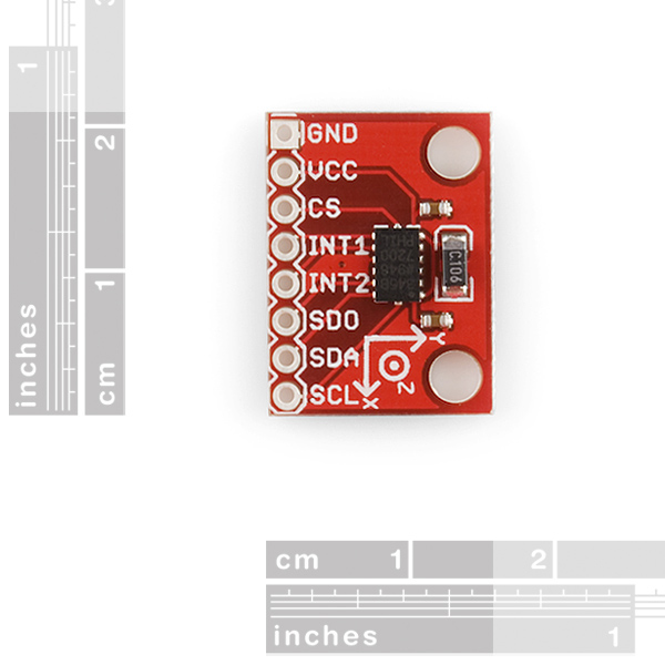
As for the location of the mounting holes, we highly recommend EAGLE (the free version will open all our files), but here's a dimensioned image that should help.
Thanks for the diagram, I had actually guessed within .05 from the helpful rulers in the product photo. I will give Eagle a try for my next round of designs.
The PicAxe-based system I'm designing will have other 5V I2C devices on the same bus, so the lines are tied to 5V with 10K resistors. A 75 cent PCA9306 seems like an easy solution from my hobbyist perspective.
BTW I'd buy PicAxe 28x2's from you if you stocked the SMD version.
Accelerometer or Gyro? I'm kinda new but have read the details on both and still not sure which is better for my project. I'm mounting the sensor on top of a tripod detect whether or not the top is swaying. I don't need direction indication, just raw movement detection, but the movement may be slight and smooth (swaying, not knocks). Which would be best or is there another type of sensor better suited for it? Thanks for any suggestions!
hey im pretty new to all this stuff... i need to just read a binary value of activity or inactivity off the chip... i know the chip has the option for set points by setting the max and min values for activity in the register as well as the sample time... but i am confused as to what they mean by register... does the sensor have any memory where i can hard set these and connect it directly to a transmitter, or do i need to keep the micro controller in the loop and reset the registers every time i power down the device?
does anyone know of a way to get more than two of these on just one i2c bus?
Thank you,
Davide
ok, the answer was easy.. http://www.sparkfun.com/products/9056
As shown in this picture, you can connect multiple I2C device to one master and there is an alternative address selection pin on this device.
er, not really. You just attach the i2c pins together. That chip could be used for the other (non-i2c) pins, though.
Nice improvement with the mounting holes, and putting the silk screen on the top. Just so everyone knows, the old one was ~1/2in wide, so this one is only a tiny bit bigger.
Why is there a via included between the IC and INT1 and INT2?
I believe it ties the ground at pin 10, 2, 4 and 5 to the ground plane on the back of the board. You can't see the rest because it's under the chip.